

This is a full example of a streaming IMA/DVI ADPCM encoder.
This example demonstrates the 32-bit AVR capabilities in real time computation. It uses the ADC feature of the microcontroller to sample a sound which data are automatically written into a buffer at a frequency given by the timer counter. During this process, the last data are readjusted and encoded in IMA/DVI ADPCM and finally transmitted through the USART by another PDCA channel.
Through this page, you can access the DSP Library documentation.
The code is based on two PDCA's interrupts.
The first PDCA channel is configured to work with the ADC. The sampling frequency is fixed by the Timer Counter peripheral and its value is 8000 Hz. Each time 252 data are received and stored into a circular buffer, as it has been configured for this application, the sequencer will encode these data with the IMA/DVI ADPCM algorithm in order to transfer them through the USART. Each data is first scaled to fit the 16-bit range and received an offset that defines the 0 absolute of the recorded sound. Then, once encoded, they are stored into another circular buffer to be sent thanks to the PDCA through the USART.
Here is a diagram summarizing the whole process:
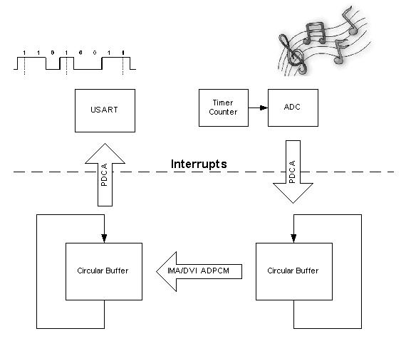
All the process is sequenced by the two PDCA interrupts which make the system working as a real time system.
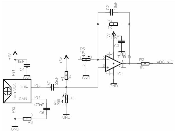
Here is the hardware interface used to acquire and adapt the sound to be recorded.
Here is a description of the protocol used to communicate between the PC and the microcontroller.
This protocol is really simple and is only a single direction transfer (from the microcontroller to the PC). The data are transmitted through 256-byte packets. The first 4 bytes of a packet correspond to the header of the packet. They give information about the initial "predicted value" and "step index" used to encode the data (those two values are used in the IMA/DVI ADPCM algorithm to encode and decode data). The last 252 bytes correspond to the IMA/DVI ADPCM encoded data.
All 32-bit AVR devices with an USART, PWM and PDCA modules can be used.
To make this example works, you will need a PC and a serial cable to connect the board to the PC.
This example has been tested with the following configuration:
 1.8.5
1.8.5