

This is a full example of a streaming IMA/DVI ADPCM decoder.
It uses the USART to receive data blocks (compressed in IMA/DVI ADPCM format) and two mixed PWM to play through a 16 bits precision sample sound.
Through this page, you can access the DSP Library documentation.
The code is based on two interrupts, the PWM interrupt and the PDCA interrupt.
At the beginning, the program will send a 'S' character on the USART line to tell the host that it is ready to start the data acquisition. The host will send first initialization parameters like the size of a block and the bit rate of the sound. Once the application acknowledge those data, the data block acquisition can start.
At the beginning of the process, the application fills all its buffers before playing any data. Then, it can start playing a data block on the PWMs. Each time a data block is read, it will check if the next one is available, if not it will wait until it is completely filled. Equally, each time a data block is filled, it will check if the next data block as already been played or not. If not it will wait, else it will start the next data block acquisition process.
You will find in section "Protocol" the whole protocol description of the data block transfer.
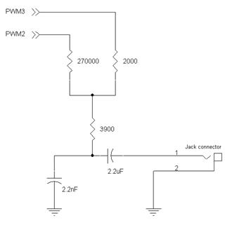
Here is the hardware interface used to mixed the two PWM, to make them act as a 16 bits DAC.
Here is a description of the protocol used to communicate between the PC and the microcontroller.
To initialize the transfer, the target have to send the character 'S' trough the USART, then the host send a block of 8 bytes described as follow:
This block will fix the length of the following blocks used to transfer the IMA/DVI ADPCM data (this length is called "block_size") and will also specify the sample rate of the sound.
Then the host wait until a byte of value 1 is sent on the line. Each time it receives this character, it will send to the target a block of (block_size + 4) bytes of IMA/DVI ADPCM data containing the sound samples. The first 4 bytes of this block contain the "Predicted Value" and the "Step Index" values used in the IMA/DVI ADPCM algorithm to compute the following data. The following data are the sound samples, coded in IMA/DVI ADPCM on 4 bits per sample.
All 32-bit AVR devices with an USART, PWM and PDCA modules can be used.
To make this example works, you will need a PC and a serial cable to connect the board to the PC.
This example has been tested with the following configuration:
 1.8.5
1.8.5