

This manual is divided into the following sections:
The Control Panel application is a demonstration application running on top of the freeRTOS.org operating system. Its purpose is to scan onboard sensors and actuators data and events (data acquisition through ADC channels) and make these available to a PC application (known as "AVR32 UC3B Control Panel PC Demo") through a simple USB cable.
The Control Panel implementation uses the AVR®32 UC3 FreeRTOS.org kernel port. FreeRTOS.org is a portable, open source, mini Real Time Kernel - a free to download and royalty free RTOS that can be used in commercial applications.
The Control Panel implementation uses the USB stack (see directory DRIVERS/USBB) and the Full Custom USB class all available in the AT32UC3-SoftwareFramework-x.x.x.zip package.
The Full Custom class is a kind of HID-like class, with the exception that the Full Custom is not supported by operating system, and thus needs a driver to run. More over, HID class works using INTERRUPT endpoints, while the Full Custom class can use either BULK, INTERRUPT, CONTROL or ISOCHRONOUS endpoints.
In this example, the PC application makes use the LIBUSB driver (http://libusb-win32.sourceforge.net/) to communicate with the embedded application. This library simplifies the work of the PC-developper since all the USB layer is managed thanks to the lib. As a consequence, the Full Custom class of the demo is easily managed by the PC application.
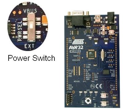
This demo was designed to run on the EVK1101 evaluation kit. The content of the EVK1101 board is:
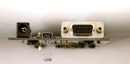
The EVK1101 board is designed to be powered by a 9V DC power supply. The EVK1101 can be configured to use one of the following two power sources:
First, the PC application shall be installed prior to connecting the EVK1101. This application can be found in the APPLICATIONS/EVK1101-DEMO/PC_APPLI directory. The application needs a Java Runtime Environment (JRE 5.0 or higher).
Both applications are available in the AVR32 Technical Library CD bundled with the EVK1101 and on atmel.com/avr32. When the installation is done, the EVK1101 can be connected to the PC.
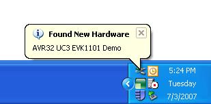
For the first plug of the EVK1101 on the PC, the operating system will detect a new peripheral.
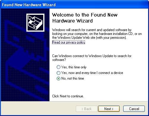
This will open a new hardware installation window. Choose not to connect to Windows Update for this installation and click `Next':
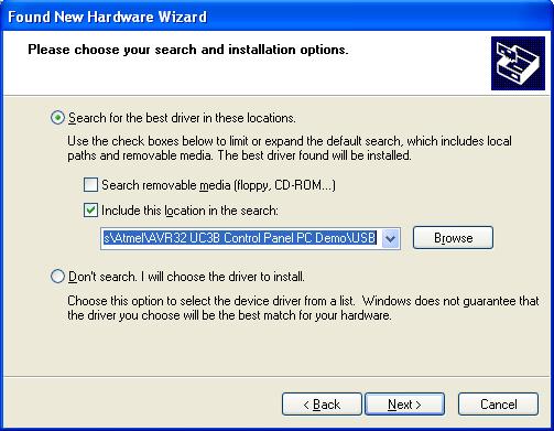
On the next screen, select "Install from a list or specific location (Advanced)" and click `Next'. Then request to search in the usb folder of the "AVR32 UC3B Control Panel PC
Demo" installation directory as shown below and click `Next':
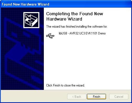
Windows will then process the installation of the driver. Once completed, click `Finish'.
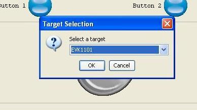
Launch the AVR32 Control Panel PC Demo application (a shortcut has been added on the desktop after the installation). For the initial start of the application, you must select the target. Choose "EVK1101" in the list. Click "OK": the application will connect to the EVK1101.
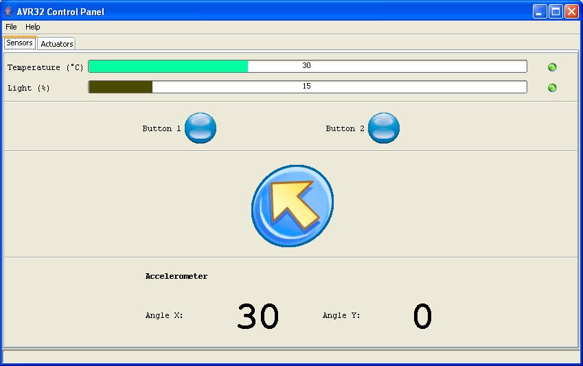
It will connect to the EVK1101 through the USB and show the status of the states of the various sensors and actuators.
The AVR32 UC3B Control Panel PC Demo shows the states of all the sensors of the EVK1100:
The actuator tab shows the state of the LEDS. User have the possibility to control each of them (note that their intensity is adapted in respect of the light sensor when tou go back to the 'sensor tab').
When the PC appli is running, if a UC3B device reset occurs, then the PC application "-> select target -> EVK1101" is not working anymore.
For further information, visit Atmel AVR32.
 1.8.5
1.8.5